My Adventures in Fluid Simulation
31 Mar 2024
I’ve been interested for some time in the processes that can be used to visually simulate fluids for some time now. In this post, I hope to explore my struggles and success during my journey into the large and complex world of fluid simulation.
The Sum of Sines
In order for a fluid simulation to run in real time, some sacrifices must be made, purely due to the limitations of computer hardware. But there are many ways to give up this detail. One of the simplest methods is to ironically to ditch the actual fluid simulation. Instead, we can approximate the behavior of the surface of the fluid by transforming a flat plane.
As this method seemed to have the lowest entry requirements, I began work on a simulation. I used my own rendering engine, Vision, for the project. The first step in the project was to draw a plane. While a plane could be treated as a single quad, I divided the quad into a arbitrarily large grid of vertices, to allow for detail as we transform it. This quad gets shipped off to the GPU, where we crunch some numbers to draw it on screen. Voila! We have successfully simulated sitting water.
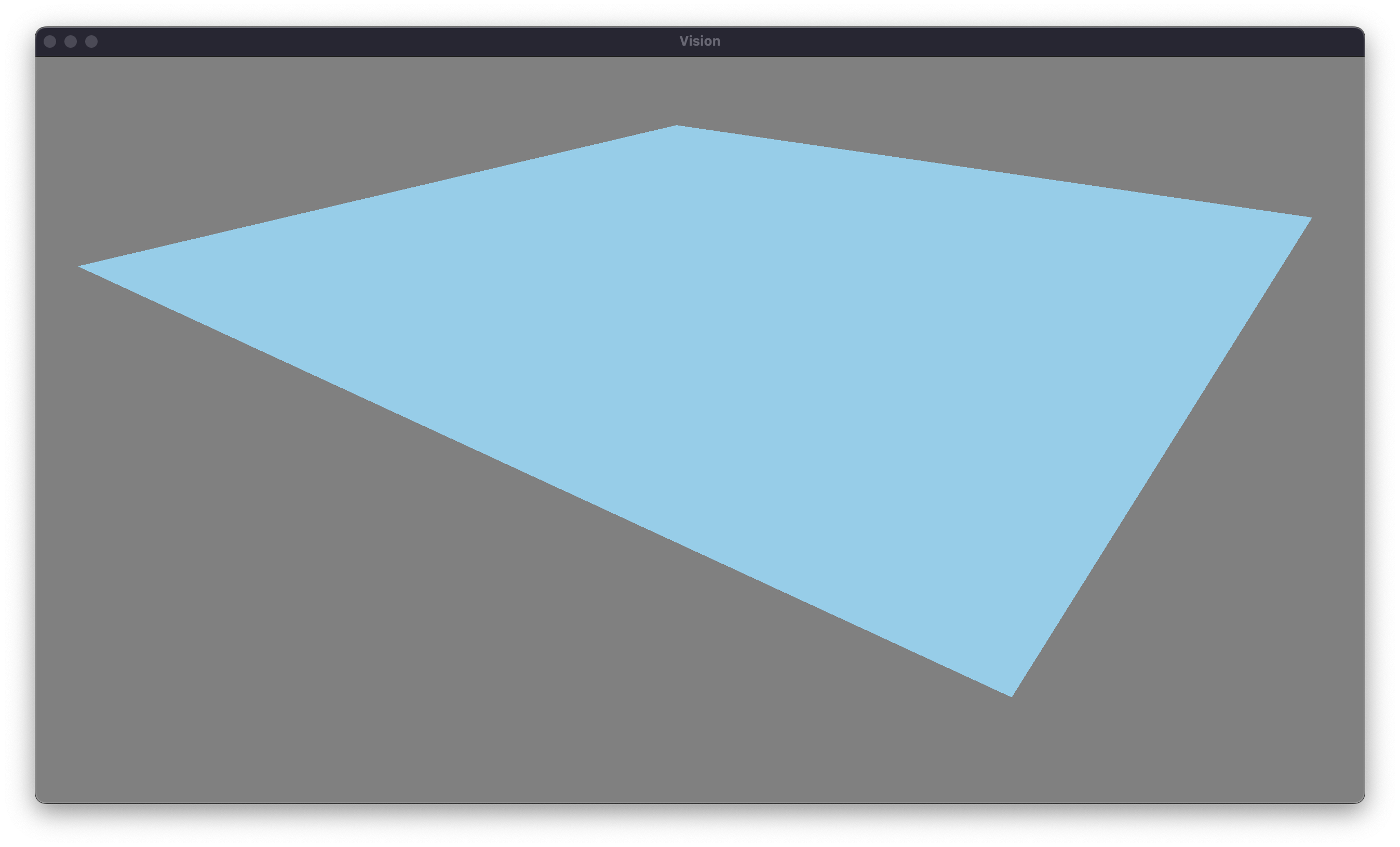
Our next step is to begin to transform our humble plane to approximate fluid. The idea is straightforward. The surface of the water is going to be wavy. By combining a few large waves, with many small waves, we are left with something that should resemble the movement of the water. Fortunately, or unfortunately, depending on your view, we’re going to have to bring some math to figure out the height of the water, given a particular wave. There are many different functions that model a wave, but the simplest is our good friend the sine wave. To model the change in height over time, we can use the general form for sinusoidal motion.
\[y(x, t) = A \sin(kx - ωt+ϕ) \nonumber\]There’s definitely a lot going on here, so let’s break it down. The first thing to note is that the height at a given point depends on two quantities: position and time. The position can be thought of as the distance from the origin of the wave (or more formally the dot product of the displacement and wave direction, since the waves flow in one direction). The second factor is the time. This makes sense as our waves are dynamic. These account for two of the terms in the equation. The other terms are the amplitude, which just scales the entire wave by some amount, and the phase shift, which moves the wave around independently of position or time. Now that we roughly understand the process by which a wave is applied, let’s more formally define a wave in the codebase.
struct Wave
{
  // Origin and Direction
  glm::vec2 Origin;
  glm::vec2 Direction;

  // Other Properties
  float Amplitude;
  float Wavelength;
  float AngularFrequency;
  float Phase;
}
With this layout, we can create a wave on CPU. Our next task is to iterate over the vertices in the plane, and offset their heights using the wave equation from earlier. While it is possible to do this calculation on the CPU, using a simple loop each frame, this approach is naive. The CPU is much better at performing serial tasks. While we can take advantage of CPU parallelization, and calculate multiple points simultaneously, we are limited by the number of cores in the CPU. Typically this is on the range of 2 to 32 in the most extremes for performant and dated CPUs.
Instead, we can can capitalize on the parallel abilities of the GPU. To give a little bit of perspective, the RTX 4090 has 16,384 CUDA cores. Each of these are less capable than CPU cores, but they gain their strength in numbers. To write code for the GPU, we use a shader proramming language, and give it to the rendering pipeline. Our program uses OpenGL, meaning that we need to write in the OpenGL shading language, GLSL. We are going to write two shaders: a vertex and fragment shader. The vertex shader is a program that is run per vertex in the mesh. The fragment shader is run per fragment, which is analogous to per pixel. In our shader, we’ll define some uniform information for the CPU to upload. In this case, we need the wave, the time, and the viewProjection matrix, which converts from 3D world coordinates to 2D clip space from our camera’s view. Here is the code for our vertex shader:
layout (std140) uniform WaveProperties
{
  Wave wave;
};

uniform float time;
uniform mat4 viewProjection;

void main()
{
  // calculate the distance with respect to the direction of the wave.
  vec2 displacement = pos.xz - wave.origin;
  float position = dot(displacement, wave.direction);

  // determine the height offset using general sinusoid equation
  float waveNumber = 6.283185307 / wave.wavelength; // wave number = 2 * PI / wavelength
  float waveInput = waveNumber * position - wave.angularFrequency * time + wave.phase; // store this
  float heightOffset = wave.amplitude * sin(waveInput);

  // offset the position by the height of the wave.
  vec3 newPos = position;
  newPos.y += heightOffset;

  // project from 3D space to 2D
  gl_Position = viewProjection * vec4(newPos, 1);
}
Our fragment shader will be very simple for the time being, only outputting a simple fixed blue color. That’s all that there is to it! We’ve managed to simulate a fluid, at least with a single wave flowing across it. One thing that is obvious at this point, is that our simulation has no lighting. Next, we will implement some lighting into the scene.
Lambert’s Cosine Law
Lighting, just like fluid simulation, can quickly become extremely complex. As computer scientists, our job is to tactfully choose where we invest our computing power. The most realistic form of lighting would involve simulating millions of rays of light emitted from their source and determining the paths they travel until some of them reach the camera. However, this is remarkably inefficient. Instead, we’re going to take advantage of a principle known as Lambert’s cosine law.
Lambert’s cosine law states the amount of light that is reflected by an object is proportional to the cosine of angle that the light vector makes with the normal of the surface. Note that the normal vector is simply a vector who is pointed directly out from a surface. To get a more intuitive understanding of this principle, consider a spotlight aimed at a stage. If the spotlight is pointing from directly above the stage, all of the light will be concentrated in a single circle, which will be very bright. However if the spotlight is aimed at the stage from a harsh angle, the light will cover a larger part of the stage, and will be dimmer in each spot on average. By doing a little bit of angle chasing, it turns out that this dimming factor is directly proportional to the cosine of the angle between the normal and the light source.
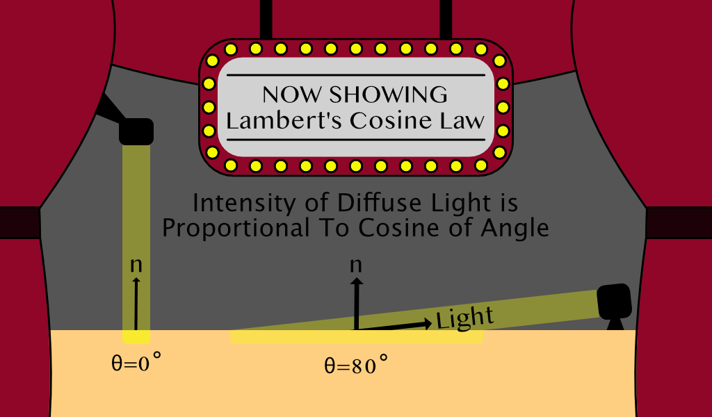
I probably spent way to much time making that visual, but hopefully that helps to make things a little bit clearer. Clearly, in the example with a greater angle of incidence, the light covers a greater area, and since the light has a because the cosine between two vectors with length one is really easy to compute. It’s equal to the dot product of the vectors, or the sum of the termwise multiplication.
\[{\vec A}\cdot {\vec B} = \|{\vec A}\| \|{\vec B}\| cos(\theta)\] \[{\vec A} \cdot {\vec B} = A_x B_x + A_y B_y + A_z B_z\]So let’s go ahead an implement this model into the fragment shader, we’ll choose some arbitary light direction, and realize that we have a problem. We don’t have normals. Typically, modeling software automatically generates normals that we can utilize. However, since we are doing the modeling in real time, we’re going to have to do all of the heavy lifting ourselves. But we can leverage another tool from linear algebra: the cross product. The cross product is not as simple to calculate as the dot product, but thankfully the GPU can make the calculation for us. The important property of the cross product is that the cross product between two vectors is perpendicular to both of them.
In our case, it is much easier to calculate two vectors that lie on the surface of the plane than the normal vector itself. The two vectors we will calculate are called the tangent and binormal vectors, which are really just the partial derivatives in the x and z directions.
\[\vec B (t) = \begin{bmatrix} 1 && 0 && {\partial y \over \partial x} \end{bmatrix}\] \[\vec T (t) = \begin{bmatrix} 0 && 1 && {\partial y \over \partial z} \end{bmatrix}\] \[\vec N (t) = \vec B (t) \times \vec T (t)\]This leaves us with the task of calculating the partial derivates of our function with respect to x and z, sticking them into these two vectors, and letting the GPU calcuate the normal vector. To do this, we need to go back to our good friend, the sinusoidal function. Note that we now have a better understanding of the dot product at this point, and since we know that it represents the magnitudes of the vectors multiplied by the cosine of the angle between them, it is more intuitive that the distance from the wave origin in the direction of the wave is equal to it. Therefore, we’ll substitute it in, and run the numbers.
\[y(x, z, t) = A \sin(k * {(x,z) \cdot {\vec d}} - \omega t + \phi)\] \[y(x, z, t) = A \sin(k (x d_x + z d_z) - \omega t + \phi)\] \[{\partial y \over \partial x} = A \cos(k (x d_x + z d_z) - \omega t + \phi) * k d_x\] \[{\partial y \over \partial z} = A \cos(k (x d_x + z d_z) - \omega t + \phi) * k d_z\]There’s no case to be made the these are nice looking equations, but we can thankfully reuse the input we calculate for the wave height in this equation again. But now that we have an equation, we have to make a choice. It is currently feasible to calculate the normal vector in the fragment shader, which would give very smooth lighting, but this will become impractical as we try to maximize the number of waves in the simulation. Therefore, we’ll calculate the normals in the vertex shader, and then let the GPU interpolate for the fragment shader. A final note is that since differentiation is a linear operator, as we add more waves, we only need to add there partial derivatives into the binormal and tangent vectors.
// calculate the distance with respect to the direction of the wave.
vec2 displacement = pos.xz - wave.origin;
float position = dot(displacement, wave.direction);

// determine the height offset using general sinusoid equation
float waveNumber = 6.283185307 / wave.wavelength; // wave number = 2 * PI / wavelength
float waveInput = waveNumber * position - wave.angularFrequency * time + wave.phase;
float heightOffset = wave.amplitude * sin(waveInput);

// calculate binormal and tangent vectors
float partial = wave.amplitude * cos(waveInput) * waveNumber;
vec3 binormal = vec3(1, 0, partial * wave.direction.x);
vec3 tangent = vec3(0, 1, partial * wave.direction.z);
normal = normalize(cross(binormal, tangent)); // normalize to length 1

// offset the position by the height of the wave.
vec4 newPos = position;
newPos.y += heightOffset;
Here is the updated vertex shader code. Lambert’s cosine law is much more trivial to to implement in the fragment shader. All we need to do is choose some light direction, reverse it, so that it’s the direction to the light, and find the dot product between it and the normal vector. We also need to the clamp the diffuse term between 0 and 1 because if the water is facing away from the light, the dot product will be negative, and negative light doesn’t exist. Finally, we have to add a constant ambient term, so that areas where the light don’t reach are still slightly colored. This ambient light can be viewed as the scattered light which bounces off all surfaces in the scene.
void main()
{
  // choose an arbitary light direcion
  vec3 lightDir = normalize(vec3(2.0, 1.0, -3.0));

  // calculate the diffuse light strength and ambient
  float diffuseStrength = 0.8;
  float diffuse = clamp(dot(normal, -lightDir), 0, 1) * diffuseStrength;
  float ambient = 0.4;

  // apply the light calculation to affect the brightness of the color
  vec3 color = vec3(0.53, 0.81, 0.92);
  fragColor = vec4(color * (ambient + diffuse), 1.0);
}
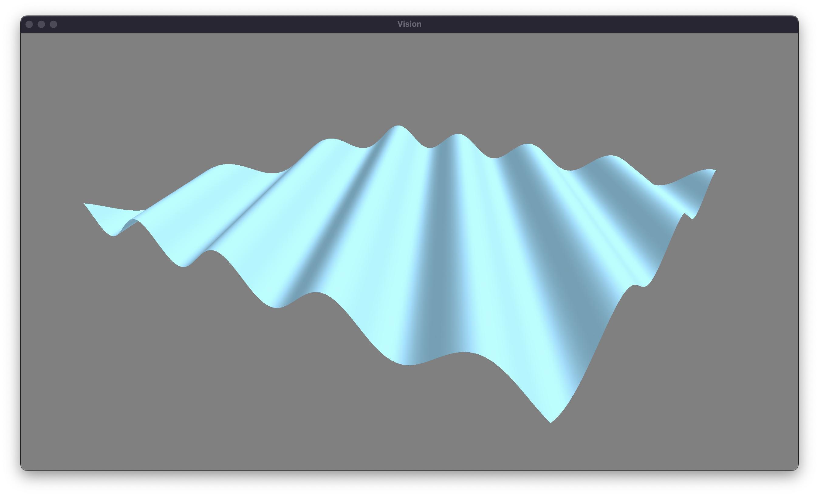
With all of those changes made, our lambertian diffuse lighting model is complete. Let’s take a look at the state of our water.
Fractal Brownian Motion
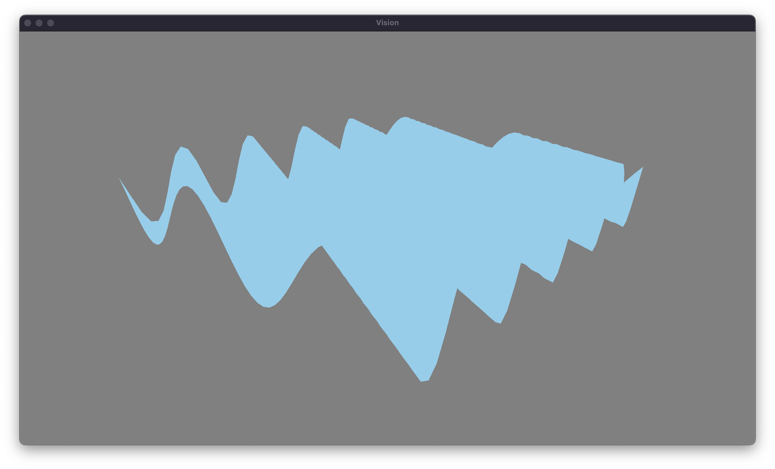
Our next task is to implement more waves. Thankfully, this is pretty straightforward. We’ll change our wave buffer to an array on the CPU and in the shader. We can assign a random origin and direction to each wave. We’ll also randomize the other properties of the waves. We can choose as many waves as we’d like, but I’m going to start with 10 waves. Let’s see what effect this has on our waves.
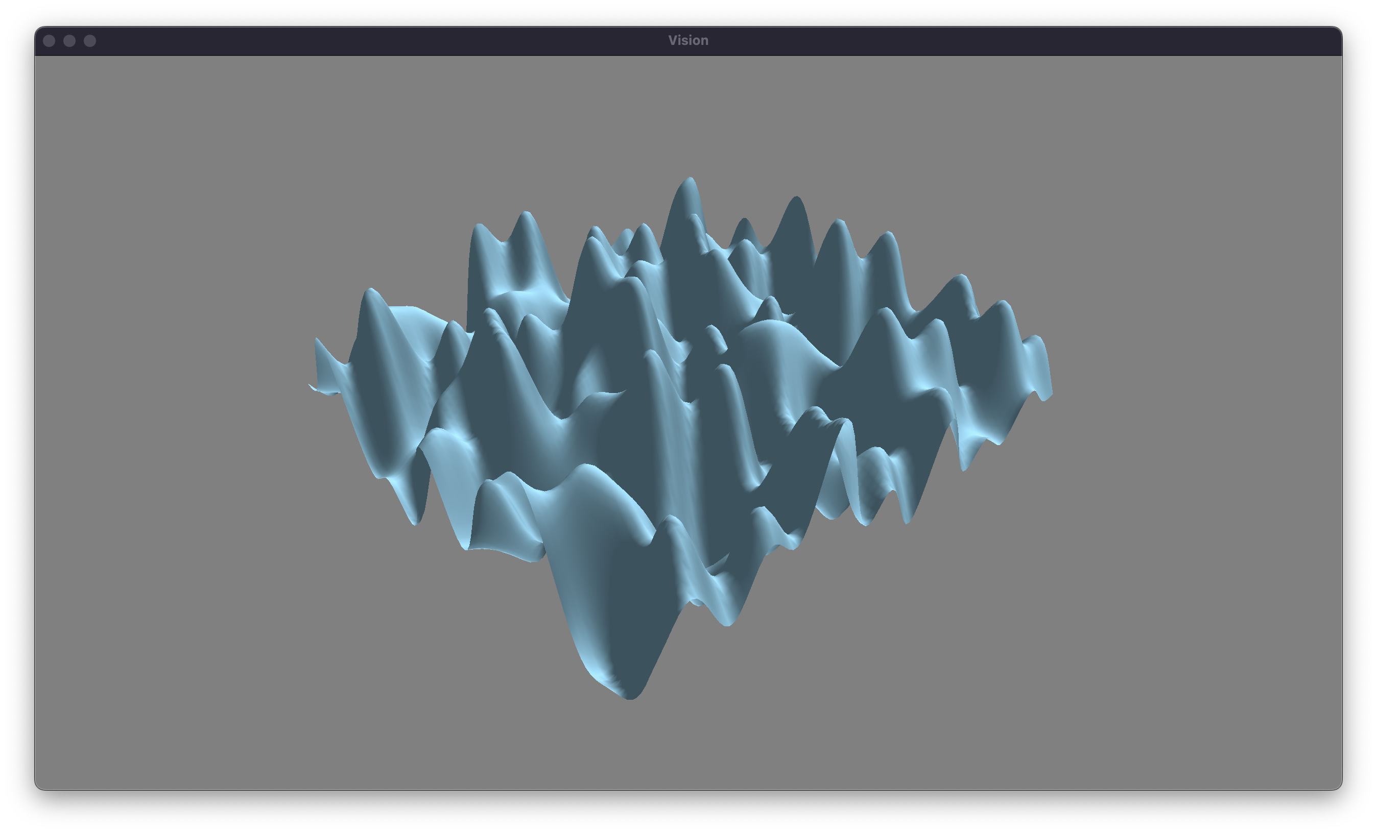
Unfortunately, we have reached a problem with this approach. Our waves are overly chaotic, and they are far too steep to appear realistic. Thankfully, we can take advantage of a tehcnique called fractal brownian motion to give a more natural appearance to the waves. Brownian motion was initially discovered by the botanist Robert Brown in 1827. He examined pollen in water (with a cover slip) under a microscope and noticed a seemingly random drift. He was unsure what caused the motion, but Albert Einstein published a paper explaining how the random collisions of atoms resulted in the drift that Brown observed. This is a slightly unimportant explanation, but Brownian motion describes all sorts of random patterns in nature. We want the surface of our water to be described randomly.
One approach to calculate this random surface is called fractal brownian motion. First, we will start with large waves that have long amplitudes. These will simulate the overall drift of the water. For the next wave, we’ll decrease both the amplitude and the wavelength of the wave by some factors, to replicate the finer details in the water. For the rest of the successive waves, we’ll repeat this process. Each wave that we add has a smaller and smaller effect on the surface. I’ll leave the exercise of implementing multiple waves in the shader to the reader, but here is how we can generate our waves on the CPU.
void GenerateWaves()
{
  float curWavelength = initialWavelength;
  float curAmplitude = initialAmplitude;
  float curFrequency = initialFrequency;

  for (int i = 0; i < numWaves; i++)
  {
    // set these properties randomly each frame
    waves[i].Origin = glm::linearRand(glm::vec2(-10.0f), glm::vec2(10.0f));
    waves[i].Direction = glm::circularRand(1.0f);
    waves[i].Phase = glm::linearRand(0.0f, 6.28f);

    // set these based on the current values
    waves[i].Wavelength = curLength;
    waves[i].Amplitude = curAmp;
    waves[i].AngularFrequency = curFreq;

    // change our values in accordance with fBM.
    curLength *= wavelengthDamp;
    curAmp *= amplitudeDamp;
    curFreq *= frequencyDamp;
  }
}
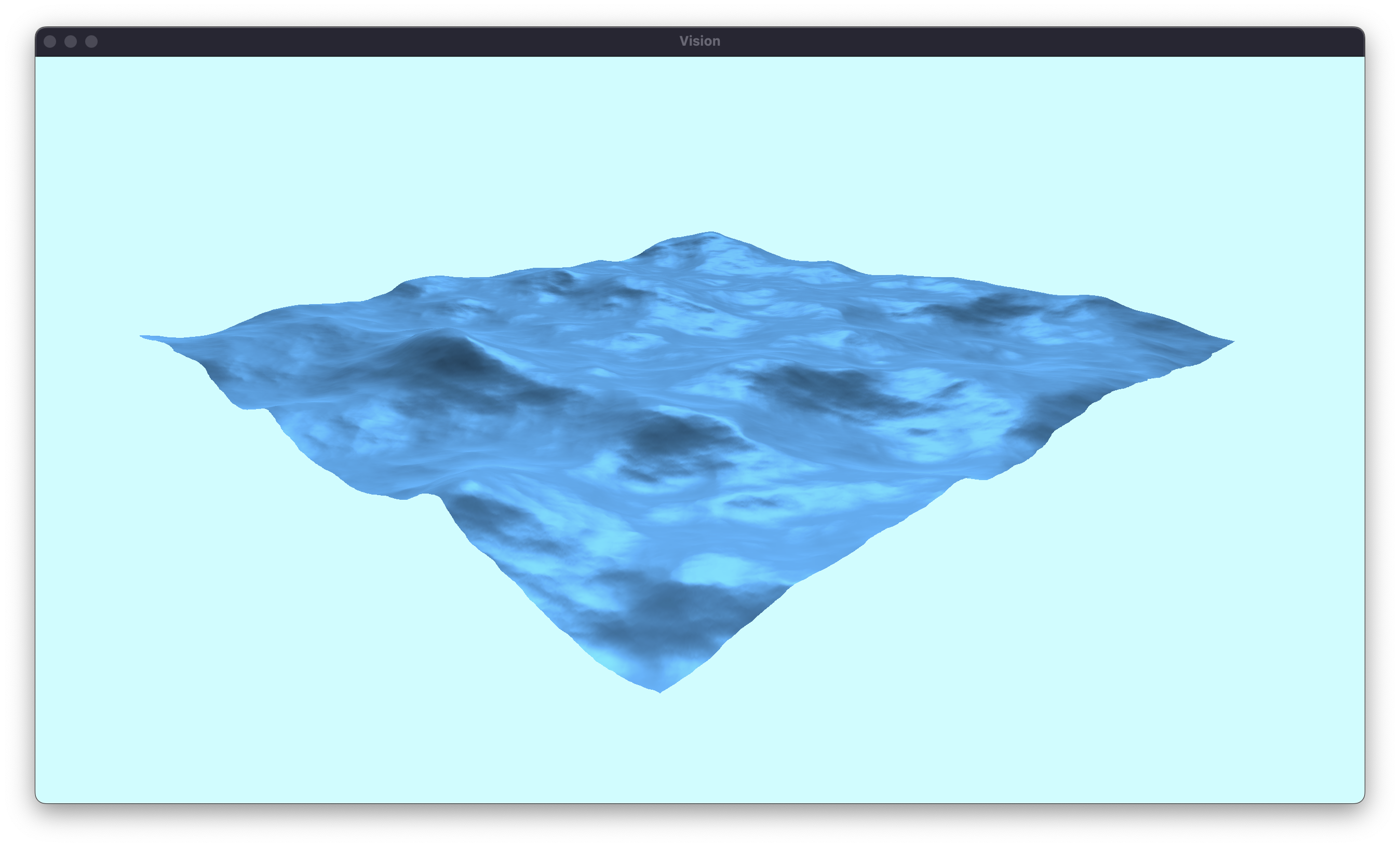
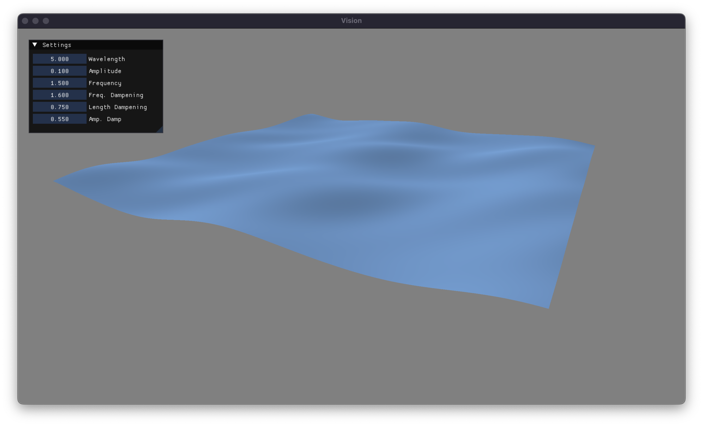
The exact values that we’ll dampen our waves with are slightly finicky. Therefore, I’ve gone ahead and implemented some UI sliders so that we can regenerate our waves without having to recompile the program. This let me fine-tune these values to get some relatively nice looking waves. I’ve also gone ahead and slightly darkened the water color. Let’s take a look at that implementing fractal brownian motion has on our waves, after a little bit of tuning.
Our waves are looking decent at this point, but there is still a lot that we can do to make them look better. In the next article, I’ll explore better lighting models, more accurate waves, and create a scene that hopefully makes you feel like you’re looking at the ocean. You can find the source code for this project on my GitHub, as well as some cool other stuff that I am working on. Thanks for reading!